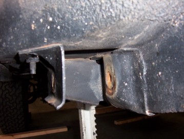
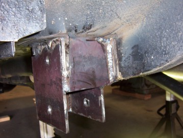
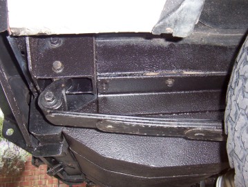
Lower rear leaf mounts
This write up covers how to get 4" of lift on stock springs or 6" if you use say a set of OME leaf springs which normally only give 2". This will mean the same smooth ride as stock springs without the increased spring rate of extra leaves. I have since changed to a 3" lower mounts by re-drilling an inch higher up and cutting the excess off the bottom of the brackets as found the stock leaves too soft and wanted to ad an extra leaf without going higher. I would recommend you do the same unless you want a higher overall height than 4". To make them only a 3" drop you must take off an inch off all measurements given below.
Lowering the mounts also lowers the anti squat as the more arch in a leaf spring the higher the anti squat. This can lead to the rear end hopping on steep climbs. It is also far better than just fitting longer rear shackles which create leverage on the weak stock mounts and only alters the height of the leaves at one end ( also altering your pinion angle ). Also the handling is effected by the change in the height relationship between the front and rear leaf mounts. The closer the two become to the same height, the looser the handling becomes. Ideally the front spring eye should be at the same height as the centreline of the axle. This gives the least rear steer possible as the suspension moves. These, and or springs with more arch, raise the roll centre ( the point through which the suspension components leans through in cornering which is measured by drawing a line from the front spring eye centre to the rear spring eye. The roll centre is at this line above the axle. ). Too high a roll centre is not good as is reduces sideways grip and causes jacking of the suspension but too low will give you more body roll. Lowering it 3" brings it down to a similar height that most 4 link rear coil suspensions systems are setup to as it is determined by where the A frame is mounted to the diff housing. Some rock crawlers even have the A frame on the lower links coming together at the axle meaning that the roll centre can even be under the axle if the upper arms are parallel. This does give a bit more body roll this way so they are controlled by anti rock bar or swaybar in these cases. Roll centre on setups with a trackbar, is at the height halfway along the length of the bar between its two mounting points. Think over these points carefully before taking on a modification such as this. Longer shackles also effect this and also cause far more rear steer when cornering or compressing one spring at a time than lowering both spring mounts. I would suggest to drill an extra set of holes at 3" lower on your plates so you can have some adjustability later on. Higher holes than that you would have to drill and tap or weld in a shallow nuts behind the holes due to interference of the frame.
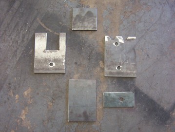
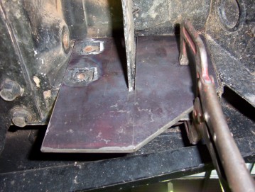
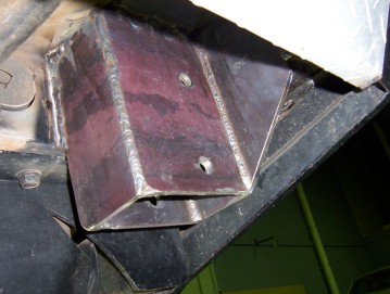
I used around 2.5 metres of 200x6 flat steel for this project. I cut it all using a 9" angle grinder for nice clean and straight cuts. Only the time an oxy was used was some of the rear shackle plates that required contained holes. Above shows the plates needed for one side of the front mounts. There were two additional bracing plates added to this as shown later. The holes were drilled 5/8" as were the stock ones for 14 mm 2.0 thread pitch stock bolts. They were drilled 4" lower and 10 mm forward than stock as I wanted the tyre to be central in the wheel well and have more of the slip yoke engaged. This also gave me the clearance I needed at the rear of the wheel well where it was just rubbing. I also fitted the upper holes so the stock bolts could still be added for a little extra support but mainly so I could return the springs to there stock height should I ever want to after cutting the bottom off the brackets. The fold at the end of the stock bracket on the side was flattened using vice grips and then finished with a hammer and dolly. Just the first part where the inner plate of the front fold was flattened as well.
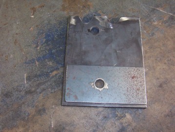
The front plates were cut to 175 mm in length and 128 mm for the inside and 131 mm wide for the outside plate, ( the inside plate is 3 mm narrower due to butting up against the front of the stock bracket ). The width was made so that the inside plate would end up level with the end of the stock nut mount plate after the back stiffening plate was added. This allows the weld for that to end up on top of the existing weld were it is thicker. The inner plate shown on the left has a U cut out so that it fits around the old nut mount. The plate was then welded square to the frame and flush with the nut mount even though it does not look like it in this shot. The outside bracket has been notched to go around the re-enforcing crimps in the top of the stock bracket. The extra plate placed on the inside here is to take up the extra width from placing the plate on the outside of the stock bracket. It is of the same thickness at 3 mm or 1/8" as it and was just stitched welded into place. The outside plate was welded right across the top including up and down the crimping slots. It was also welded fully vertically to the stock plate at the front before the front plate was added and then welded to this also.
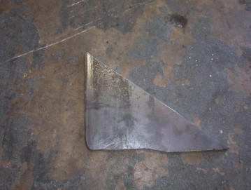
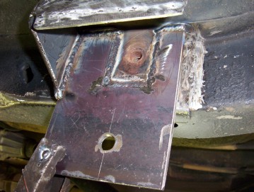
I found setting up the frame perfectly level left to right made it easier to make sure plates were square between the inside and outside. The rear plate was added between the plates to stiffen up this area and is fully welded to the new plates as well as on top of the old weld for the nut mount. All outside joins are corner to corner welds where possible. At no time in this project is weld placed on the single layer floor panel and only to the existing stock mounts welded to it. A bracing piece was cut out to go from the frame to the bottom outside corner on the new bracket. It extends to just short of where the frame overlap ends and is stepped to take in the change in shape.
By placing the brace at this angle it stiffens it both planes at once and also deflects anything past the bracket. On the inside a left over piece cut from the other plates length was added to fill in the are between the new plate and the frame as shown above right.
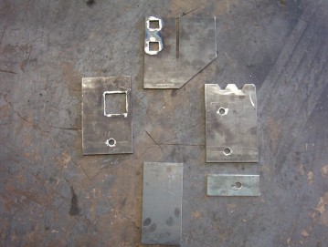
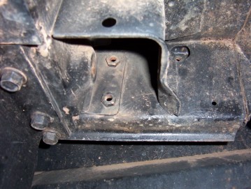
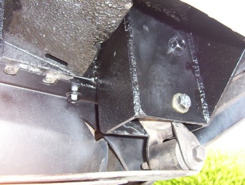
The rear brackets came out as shown. They were 200 mm long and 130/127 mm wide for the outside/inside to go from the front plate to the new back plate. The stock bracket was also straightened as the front one but a small notch in the front corner is needed to get it nice and flat around the corner. The rear plate has a slot to slide around the stock bracket and two holes to fit over the captive nuts that hold the stock rear bumper on. It was made to extend all the way to the join between the back and inner side panels. This is a very weak area and prone to cracking around the spot welds so this plate will now strengthen this area. I also fully welded the join before placing the plate in place. The plate was made to stop at the edge of this weld so I would welding over the top of this join when attaching it.
Make sure you place the level across the bottom of this plate before welding into place. It was fully welded to each side of the slot as well as around each nut and down each end of the plate. Another weld was also placed along the back of the plate along the bottom fold of the old back panel. I could just get in there between the plate and the bumper without taking it off. Leave a small area un welded in the middle so any moisture that has got in there can drain out. I did seal along the very top of the plate to keep this to a minimum. The other plates are then welded to the plate as well to the stock bracket just like the front. The yellow arrow points to the one of the vertical welds placed in before the end plate was put in place. Don't forget to add the 3 mm packer plate to the inside of the outside plate before welding it into place.
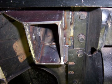
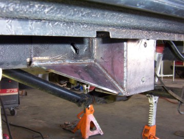
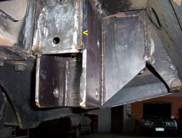
You can see the corner to corner weld on the outside and it is also welded on the inside as well. Be very careful when welding the front plate to the frame as it is only single thickness there. Don't weld to the single thickness floor any where as like the front one. A brace was added once again between the inner plate and the frame made from scrap. Just make sure you make it narrow enough so that you are welding on top of the double thickness part.

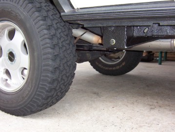
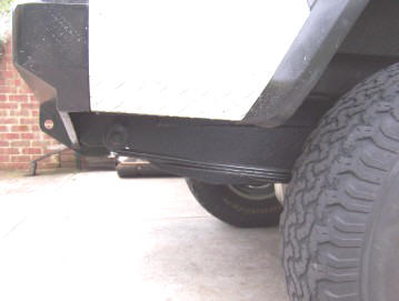
So here you see the finished product. It is much stronger than what was in there and the ride and travel is excellent. I do have a little bit more body roll from the lower roll centre and mainly the much softer spring rate. Don't forget the roll centre is now similar to a coiled rear end on a ZJ etc. It can still weave at highway speeds sharply and it is still stable.
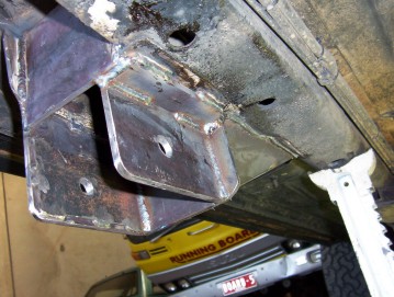
Above and below shots are from later on when I added a main leaf from an old XJ leaf pack with the eyes cut off to the spring pack. This gave me just over an inch of extra height which I didn't want. So I drilled new holes in the brackets a inch further up and cut off the extra from the brackets. I added this extra leaf as the ride was a bit too soft without and after adding my long range fuel tank, would drop too much when filling it. I have found this rides really well now and is now the same as the coil front and handles better too. Keeps the rear shackle mount above the towbar too. I would recommend this 3" drop and the extra main leaf for the total of 4.5" lift over dropping the mounts the full 4" with a 1/2" packer I had before.
Remember also there is more to do with this lift than just the mounts. The bumpstops must be dropped to stop over compressing the springs ( I used Sport bumpstops which are 1" longer than standard along with tubing above them ) plus a combination of raising the axle shock mounts and lowering the top ones similar to the fronts so I turned the lost up travel into extra down travel.
I have since added airbags so I don't lose height when fully loaded with my offroad trailer in tow and ARB fridge in the back. I fitted a kit from Airlift #59507 with the best pricing I found from the same site. The same kit is sold under the Polyair brand here in Australia #34007. Here you can see how it is installed. The airbag top bracket will be added upside down to suit my 4" lift.
[Index]