Adjustable MAP sensor
The MAP sensor ( Manifold Absolute Pressure ) has a 5 volt input and then reduces this voltage according to throttle opening, altitude etc and sends the signal to the ECU. So by supplying a higher or lower voltage, the return signal is varied by the same amount. This can be used to fine tune the air fuel ratio at throttle openings over 80% and before the engine is up to temperature. This can be an aid in getting better fuel economy under those conditions but I have also used it to stop engine pinging after fitting a stroker engine for a customer. Many stock engines also do this when running lower octane fuels. So what I did was follow Dino's write up and take 12 volts and run in through a potentiometer and a voltage regulator so I could adjust the input voltage to anything I wanted. If you supply a higher voltage, the effect is that the injectors stay open longer so it is richer and vice a versa. You can however only tune from 80% throttle opening to wide open throttle when the ECU is in open loop mode. This is because below that the ECU will keep it as close as it can to lambda 1 or stoichiometric which is 14.7 parts O2 to 1 part fuel. At WOT throttle though it ignores the o2 sensor and relies on the map sensor to set the length of time the injector is open. The other time is when you are running cold before the thermostat has fully opened where the O2 sensor is not read either before it goes into closed loop mode. This is a big reason not to run a lower temp thermostat as the ECU will be waiting for it to reach operating temp but it never gets there if a lower one is used effectively keeping the ECU in open loop mode where is does not read the o2 sensor.
Part list needed below which can be bought from Radio Shack, or here in Australia, Dick Smith or Jaycar:
Multi-turn (15) Cermet Potentiometer 1000 ohm
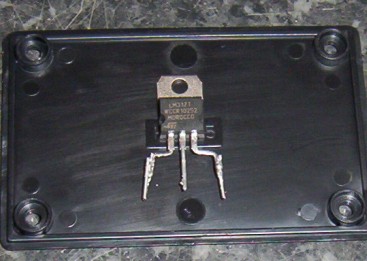
LM317T Adjustable Voltage Regulator
220 ohm metal film resistor
Mini Terminal Strip
Heat sink for Regulator
SPDT toggle switch
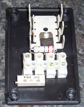
You start with the regulator by bending the two pins outwards and then down so it can be inserted into the terminal strip. I had to extend them by just soldering on some wire cut from the resistor. It is then placed into the terminal block No. 2, 3 & 4. Only No.4 should be screwed down at this point and the other two when the resistor is added.
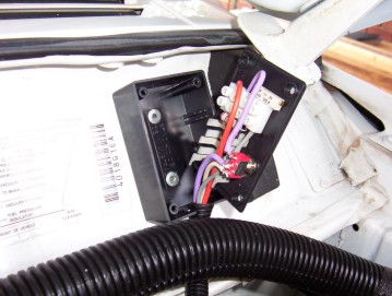
Time to add it to the box you wish to keep it in. I just used a small one sold at the electronic store. I used a rivet from the other side to hold the heat sink to the regulator and keeps the hold thing in place too. You will see also in the next shot the toggle switch has also been put in place. The grey wire at No.1 goes to earth on the firewall. The purple wire in No.3 runs the modified voltage to the switch. No.4 has the 12v input.
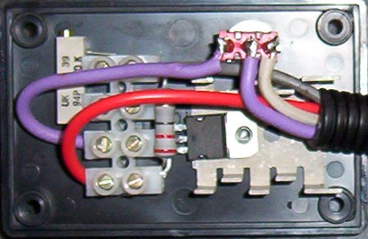
You can see here how the purple wire from above has been terminated at the switch. The second purple wire to the centre of the switch is the return voltage be in modified or stock voltage depending on the switches position. The dirty white wire on the last switch position is the original 5v that supplied the MAP sensor.
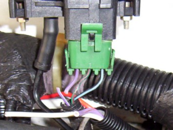
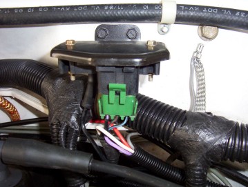
Here above you can see how the stock purple wire with a white stripe has been cut that went to the MAP sensor. This is the original 5v supply. The end coming from the harness gets the white wire soldered to it and goes to one side of the switch. The other end going to the MAP sensor has the purple wire from the middle of the switch soldered to it with either the modified or stock voltage suppling the MAP sensor depending on the switches position.
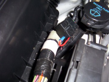
I found a good 12v source right next to the ECU and washer filler at a plug that was not being used. This is the diagnostic port and is ignition only which is what you want and already fused. The box I mounted next to the bonnet hinge to keep it away from heat and water.
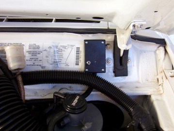
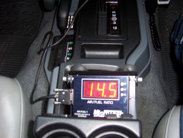
You can see above how it fits neatly there. Now for the tuning part. I had it easier than most due to the fact that a good mate of mine Peter from FMA car and truck repairs lent me his wide band exhaust gas analyser so I could test the voltage I needed to run a full throttle. The picture shows what the ECU has it set at idle. I set mine at around 12.7 at WOT which is considered safe and not wasting fuel or having it too lean to burn valves etc. If you don't have a meter you could get very close just adjusting until pinging is just heard and then richening it back up a bit more or vice a versa if trying to get rid of pinging in the first place. Below will give you an idea of different settings.
| A/F RATIO | DESCRIPTION |
|---|---|
| 6-9 | EXTREMELY RICH: Black smoke and low power. |
| 10-11 | VERY RICH: Some supercharged engines run in this range at full power as a means of controlling detonation. |
| 12-13 | RICH: Best power A/F: Un-supercharged WOT. |
| 14-15 | CHEMICALLY IDEAL: At 14.6 the A/F is at the theoretical ideal ratio with no excess fuel or oxygen after combustion. Good A/F for part throttle cruise and light to moderate acceleration. |
| 16-17 | LEAN: Best economy A/F ratio. Borderline for part throttle drivability (worse than borderline if EGR is used). |
| 18-19 | VERY LEAN: Usual lean limit (Driveability). |
If you do not have one you can read the voltage from the O2 sensor to give you a rough idea of the best setting. It will need you to have a nice long hill that you can hold it at WOT to get some the voltages needed. It will fluctuate a lot so be prepared for it and it is best to have some one read it for you. Remember you must have the engine up to full temperature so that the ECU is in closed loop mode and reading the O2 sensor and that is at the right temperature too.
These charts above will give you some idea of what to shoot for. All you have to do is connect a wire long enough from the O2 plug to your digital multimeter inside where your passenger can read it while testing. Just make sure that that wire never touches ground as it will damage the sensor. The negative lead of the multimeter goes to ground so you can read the voltage changes. You will find 4 wires on the O2 sensor. Two are for the heater + & - and the other two are ground for the sensor and output to the ECU. The grounds will be easy to measure and the two positives will have one at 12v for the heater and the other will be at .450 volts when the engine is cold and in open loop mode will running. The chart below shows a typical three wire sensor which uses the exhaust as the other ground.
After reasoning operational temperature, the reading will begin to start changing from near 0v to 1v. If this happens all is as it should. It should vary quickly and if not change your sensor. If you do not get a change by the time your thermostat has opened, then there is a problem and could be you are running too cold a one so it is staying in open loop mode. The range is as follows: 3mV being the leanest, 1V being the richest. Part throttle does not matter so much as the ECU always keeps it somewhere in this range depending several on variables and inputs from other systems sensors. At Wide open throttle the MOST desirable voltage should be somewhere between .850mV an .900mV Make adjustments accordingly to reach the desired settings. Remember, the lower the voltage the leaner, the higher the voltage the richer.
To give you some ideas of what to run here is mine and some others that have this setup and what modifications that will influence the voltage:
| Voltage | Modifications | Owner |
| 4.25 | Ford 24 lb injectors, 62mm T/B and spacer, Headers with 2.5" system, Ported head, 9.25:1 compression, JET stage 2 PCM, FIPK | Dr. Dyno |
| 4.65 | 2000 intake & injectors, T/B spacer, Adjustable fuel pressure regulator at 47 psi, Headers with 2.5" system and Bored 60mm T/B | Gojeep |
| 5.15 | Ford 24 lb injectors, 4.6L stroker, 65mm T/B and spacer, Headers with 2.5" system, Ported head, 9.25:1 compression, Crane 260/272, JET stage 2 PCM, FIPK | Dr. Dyno |
| 6.00 | Ford 24 lb injectors, 4.6L Titan stroker, 60mm T/B, Headers with 2.25" system, 9.25:1 compression, .420 lift Clevite cam, Stock air box and filter, 1995 XJ with stock 39 psi fuel pressure. Engine only 200 miles old and still breaking in. Solved pinging problem. | Gojeep |
[Index]