Fitting a D44 rear axle
Due to the inherent weakness of the stock D35 axle housing and also the C clips which would allow the whole wheel and axle to depart the Jeep should a axle break, I fitted up a brand new ( NOS ) D44 for a MJ Comanche, ( Cherokee pickup ) in place of it. Easier still, if using stock shock and spring mounts, you can also just bolt in a D44 from a 87-89 XJ that was often found when the tow package was ordered. These are stronger than the D44's fitted to the TJ Wrangler's as those have the smaller and thinner axle tubes the same as the D35. Surprisingly considered weaker than a ZJ D44 with a aluminium centre and weaker still than a Chrysler 8.25! Details gained from JP Magazine axle comparisons in August 2007 edition.
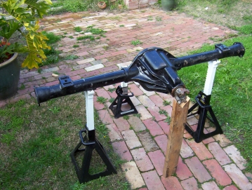
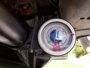
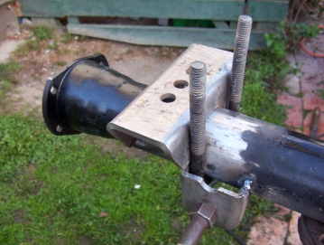
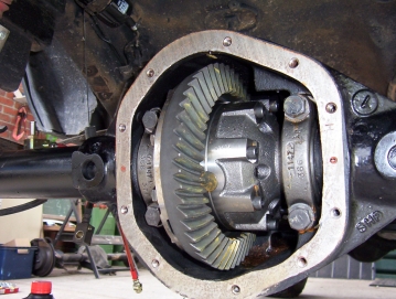
Even though this was a new bare housing having never been used before, it came with cast spring perches that needed to be removed as they are on the underside on a MJ, ( axle upside down in photo ). Once the axle was clear of them, it could be placed under the Jeep along with the new RE anti wrap spring perches to work out the correct angle and position. The spacing will be determined by the spring spacing best measured off the frame. Centre it by comparing via the frame position or the distance in from each end. As I had fitted a SYE at the same time along with a new driveshaft of the same design as the front, ( but 45 mm longer ) with a double cardon joint, the angle was setup next to accommodate this. A angle gauge was attached to the flat part next to the diff cover to read pinion angle as above.
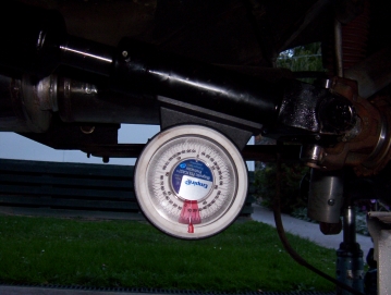
It was then compared to the angle finder when placed on the driveshaft. The axle was rotated until the pinion was 2-3 degrees less than the driveshaft, ( the pinion was pointing 2-3 degrees below the centre of the output yoke centre ). This meant on mine the angle finder next to the diff cover was reading 81.5 degrees or 8.5 degrees off the horizontal ( 90-81.5 ), and the angle finder on the driveshaft was reading 11 degrees off the horizontal. This gave a 2.5 degree difference right in the middle of the 2-3 degrees recommended to level out the pinion rise during acceleration. The perches were tacked on in this position and the axle removed so the shock mounts could be added.
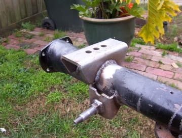
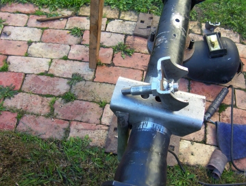
The shock mounts were made from Ryan's idea to cut a standard single spring perch in half and then a special shock bolt, NAPA part # P-19, bolted and welded in. Remember though that you must have lowered the bumpstops the same amount as these are higher than stock mounts or run shorter shocks with extra compression. Make sure the nut on the back end up with the sides vertical so that the U bolts can pass by. The edge of the shock mount lines up directly under the spring perch. The angle of the shock mount was made so that is was vertical when the spring perch was at the same angle as when under the Jeep. It was then fully welded on doing only one inch long welds at a time before allowing to cool and welding on the opposite side of the axle to balance out the heat. This keeps the axle nice a straight.
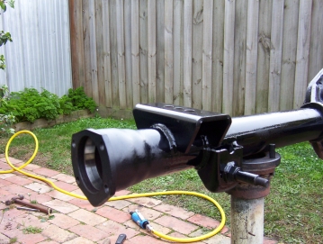
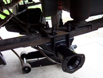
Check to make sure that the end of the welds do not interfere with the U bolts and use a die grinder to clearance the end of the welds if needed. The axle was then given a shot of stain black and then bolted in with new U bolts and nuts which I had made at the local spring works. Make sure you check the tension after a settling in period.
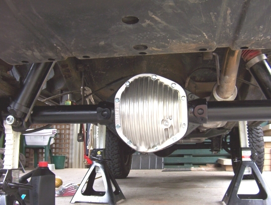
A big thank you to Ryan Brown of www.rawbrown.com who got the axle for me and then fitted it up with a Detroit Locker, 4.56 Yukon gears and US Alloy CrMo axles. I also added to this a made in USA forged alloy cover from Concept Patterns. This gives the extra volume and cooling as well as a drain plug.
[Index]