Heavy duty
Headlight Loom
This is a good upgrade even for stock head lights
but even more so for those who run higher wattage globes ( bulbs in the US ).
Running higher watt globes on stock wiring will cause the wiring etc to over
heat and cause the lights to black out! Not what you want when rounding a bend
in the middle of the night at speed. Consider these facts on voltage drop. A
Halogen headlamp is rated to produce 100 % of its rated light output at 13.5V.
When voltage at the headlamp drops by 5 % to 12.82V the light output drops to 83
% of normal. When voltage drops by 10 % to 12.15V the light output drops to just
67 % of what it ought to be. A mere 1.35V of lost voltage has robbed you of 33 %
of your light output. And it gets worse as voltage is further reduced. These
figures come from a leading headlamp manufacturer and
this site. This setup will allow the use of 170/100W
globes to be used safely. You can use this setup for any brand of vehicle as you
don't even need to know anything about the wiring setup so long as they run H4
globes as all the switching is run from the plugs at the back of the headlight.
Even other globe types can still use this setup so long as you plug your switch
wires to trigger the relays into the high and low beam terminals.
|
Item |
Amount |
Description |
 |
520 cm |
You need the red 6 mm wire for supplying
both the relays and the headlights high and low beam. 6 mm wire
falls closest to 10 AWG wire and is rated to carry 50 amps. |
 |
260 cm |
This is black 6 mm wire to supply the
ground for the headlights. ( 10 AWG ) Use only automotive wire for
all connections or if in a salt area,
marine
boat wire is even better. |
 |
160 cm |
This wire is only used to ground the
relay and as a switch wire from the old headlight plug. I used 2.5
mm wire which is around14 AWG. |
 |
4 of |
To fit the 6 mm or 10 AWG wire to the
battery terminals for ground and to the front of the engine fuse box
for positive. Check your batter clamp bolts size. Mine were 1/4" |
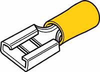 |
6 of |
To connect the 6 mm or 10 AWG wire to
the relays |
 |
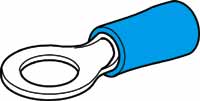
4 of |
To connect the 2.5 or 14 AWG wire to
the relay for the switch and ground wires. |
 |
2 of |
To connect the 2.5 or 14 AWG wire to
the old headlight plug for the relay switch wires. Can also use a
male H4 plug to make it even neater.
http://www.rallylights.com/detail.aspx?ID=1421 |
 |
2 of |
To connect the 2.5 or 14 AWG wire to
ground from the relays |
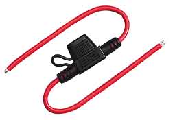 |
2 of |
Waterproof inline blade fuse holders and 30 amp fuses ( depends on
the wattage of bulbs used ). |
 |
2 of |
New H4 headlight plugs. Buy the ones
without wires already on them from a auto electrician or if in the
USA,
http://www.comagination.com/ . Also here in the USA,
http://www.rallylights.com/detail.aspx?ID=1242 |
 |
2 of |
Used one 40 amp for the high beam
and one 30 amp for the low beam. It makes it easier to identify them
but even a pair of 30 amp ones are enough for up to 130 watts with
still some head room. If you can, buy them with 5 pins ( 2x pin
87 for left and right headlight connections ) NAPA #AR274 Otherwise
just put both wires together into the one spade terminal. Or as I
have done since, two relays for each headlight, ( one for hi and one
for low per headlight ). That way more current and can only loose
one high or low per headlight at a time if a relay fails or fuse
blows. |
 |
2 of |
You need 3 meters of 13 mm or 1/2"
split conduit and only 1/2 meter of 10 mm or 3/8" as well for the
switch wires. |
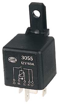
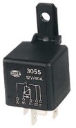
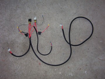
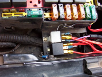
I started by wiring the relays. The black 30
amp relay on the left is for the low beams and the grey 40 amp one on the
right is for the high. You can just use two 30 amp ones but like using
a 40 amp one for the high beam to give plenty of head room for running 170w
globes. If you are running 2 relays for each headlight, you will need to
double up each one and run the switch wire to both pairs. Remember all wire lengths are based on the
fact that you fit them exactly where I have and on a Jeep XJ Cherokee. If you choose another location
for the relays all the measurements will have to change.
Wire A ( one for each relay ) above goes from pin 30 on the relay
using a yellow female spade at one end, to
power using a 1/4 ring terminal for the front of the fuse box at the other. This carries a 30
amp
blade fuse holder with water proof cap and came complete with the 6 mm wire needed
pre-assembled.
Wire
B ( one for each relay ) runs from pin 85 to ground on inner guard panel. It is
2.5 mm wire 20 cms long with a blue female spade at the relay end and a ring
terminal at the other to a ground screw.
Wire C runs from pin 86 to
the old headlight plug low beam socket ( top most terminal on the plug ) using a
blue male spade at one end and a blue female spade at the other for the relay.
It is 2.5 mm wire ( 14 AWG ) 60 cms long.
Wire D runs from pin 86 on the grey relay to the
high beam terminal on the old headlight plug using a blue male spade at one end
and a blue female spade at the relay end. It is 2.5
mm wire ( 14 AWG ) 60 cms long.
Assemble the headlight plugs as shown above
right. You will need three wires 60 cms long for the right headlight and three
200 cms long wires for the left side. Two red wires each side with yellow female
spade terminals at the relay end and the new headlight plugs female push in
terminals at the other. One black for each side with headlight plugs female push
in terminals at one end and yellow ring terminals to suit the negative battery
terminal bolt at the other.
I soldered and crimped them before pushing them into the holders headlight
holders.
Now time to join the relays to the headlight plugs. Wires not marked are
those already shown above in the first photos.
Wire E runs from the right headlight plug to pin
87 on the grey high beam relay and is 6 mm or 10 AWG wire 60 cms long.
Wire F runs from the right headlight plug to pin
87 on the black low beam relay and is 6 mm or 10 AWG wire 60 cms long.
Wire G goes from the right headlight plug to
ground on the battery and is 6 mm or 10 AWG wire 60 cms long.
Wire H runs from the left headlight plug to pin
87 on the grey high beam relay and is 6 mm or 10 AWG wire 200 cms long.
Wire I runs from the left headlight plug to pin
87 on the black low beam relay and is 6 mm or 10 AWG wire 200 cms long.
Wire J runs from the left headlight plug to
ground on the battery and is 6 mm or 10 AWG wire 200 cms long.
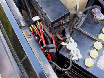
I encased the wire in split conduit to tidy in
all up as well as making it easier to run keeping it together and protected. The
three thick wires together in the 13 mm conduit for both left and right
headlights and the two switch wires together in a 10 mm one. I
mounted the relays on the support bracket for the fuse box. You can see also how
the relay grounds ( pin 85 ) use the fixing bolt of the same bracket as well.
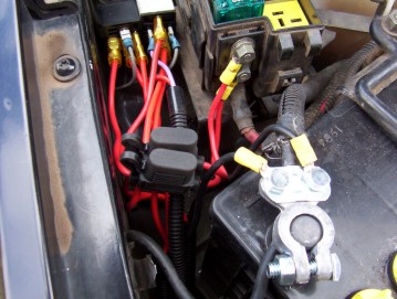
The two power supply wires from the relays ( pin
30 ) attached to the front of the fuse box where the power supply from the
battery is fixed. The cover slips back over nicely leaving them protected. The
two headlight ground wires from the plugs attached directly to the battery
terminal making sure the best possible supply. A body ground is not as good for
this many amps.
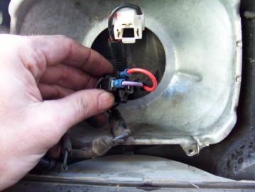
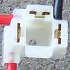
The photo above shows the switch wire connections
to the old headlight plug. The red wire ( wire C from the top photo ) goes in
the top most terminal and then to the black low beam relay on pin 86. The purple
wire ( wire D from the top photo ) goes in the left terminal and goes to pin 86
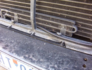
on the grey high beam relay. To run the loom across to the other headlight I
placed it behind the grill support frame as shown. It tucked in nicely between
that and the auto cooler brackets as shown with the left cooler bracket done and
right cooler bracket still not to show where it runs.
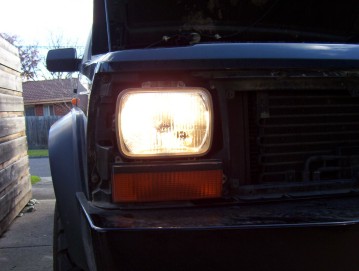
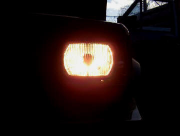
Even though the above photos have different exposures, they really were that
different with the left photo showing the new wiring and the right one still
plugged into the old wiring. They were much brighter and a whiter than before
now that there is no voltage drop. These were running 130/90W globes and if left
on high beam for too long they would cut out all together. Now no such problem
happens.
I have also been made aware that on some models with day time running lights (
DRL ) that it can cause problems. The easiest way to fix it is to disconnect the
DRL module. This will though stop the high bean light from coming on so to get
that to work, just jump the no.1 and no.4 terminals on the plug from the DRL
whose plug is pictured below to suit 90-98 years.
[Index]